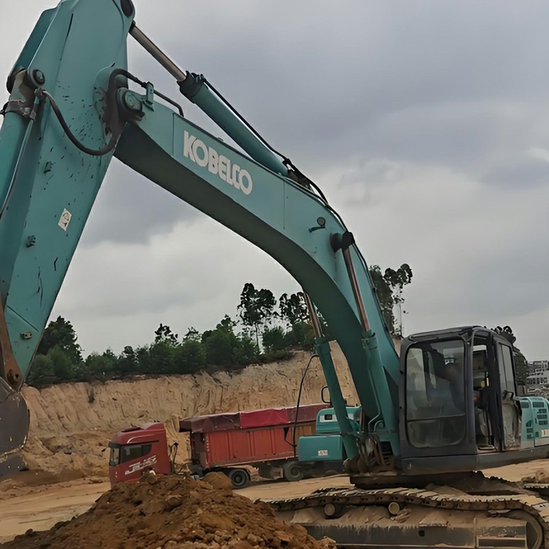
Kobelco’s 20-metric-ton and 30-metric-ton excavators, equipped with Hino J05E and J08E engines, rely on precise and complex sensors to monitor emissions, fuel pressure, temperature, and engine speed. This guide provides a detailed overview of the exact locations, functions, and common diagnostic trouble codes for each key sensor, helping you quickly troubleshoot excavator issues.
Common Fault Codes: P0405, P0406, P0407, P0408, P0489, P0490
Location: Located on the EGR unit, appearing as a silver cylindrical component on the side of the engine facing the counterweight.
Function: Controls the volume of exhaust gas entering the intake pipe, recirculating a specific amount to lower combustion chamber temperatures, improve engine operating efficiency, and reduce emissions.
Figure 1: EGR Valve Location on Hino J05E/J08E Engines
Function: Controls the inlet diesel fuel flow into the supply pump. A malfunctioning SCV valve will cause engine output to drop or even stall. Sticking is usually caused by fuel contamination; clean the fuel system and replace fuel filters. If unresolved, check terminal resistance with service tools.
Figure 2: SCV Valve Mounted on the Diesel Supply Pump
Location: Located on the high-pressure common rail.
Function & Diagnostics: Detects fuel pressure in the rail and sends electrical signals to the ECU, which regulates the SCV to control pump output. When pressure spikes abnormally (e.g., reaching ~200MPa), the pressure control valve opens to return fuel to the tank, closing once pressure drops to ~50MPa to maintain stability. Troubleshooting: check sensor wiring for moisture/looseness; measure terminal voltages at ECU and sensor sides. If the pressure control valve sticks, it triggers high/low pressure alarms; momentary debris might clear upon engine restart.
Figure 3: Common Rail Pressure Sensor on High-Pressure Rail
Common Fault Codes / Symptoms: Low oil pressure warning
Location: Located on the engine oil cooler.
Function: A normally closed pressure switch. If low oil pressure is detected while the engine is running, it triggers a buzzer alarm and automatically shuts down the engine.
Figure 4: Engine Oil Pressure Sensor on the Oil Cooler
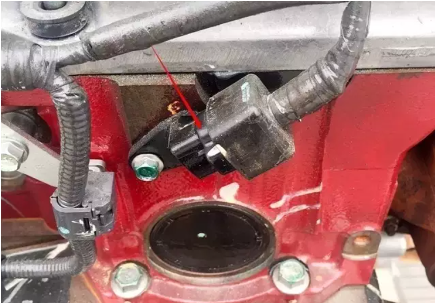
Location: Located at the lower edge of the flywheel.
Function: Used to provide engine speed feedback to the CPU. In the event of an abnormality, it will control the hydraulic system to reduce engine power or cause the engine to shut down.
Figure 5: CPU Main Speed Sensor Located at the Flywheel Lower Edge
Common Fault Codes: P0201, P0202, P0203, P0204, P0205, P0206
Location: Mounted on the engine cylinder head.
Function: Maintains electrical continuity between the injector solenoid valves and the ECU, controlling injection start and stop timing to regulate injection advance angle, engine speed, and torque.
Figure 7: Injector Harness Connector on the Cylinder Head
Location: Located on the diesel supply pump, adjacent to the SCV valve.
Function & Diagnostics: Controls fuel heater operation and protects the fuel system. Inspect for loose wiring first. Check resistance across ECU terminals: normal resistance is ~2.45 kΩ at 20°C and ~1.15 kΩ at 40°C. Replace if faulty.
Figure 8: Fuel Temperature Sensor on the Supply Pump Near SCV
Function: Used to provide the ECU with signals for engine speed, crankshaft angle, and camshaft angle, enabling the ECU to accurately determine timing information. If the sensor malfunctions, the engine speed may drop or become abnormal.
Figure 9: Main Speed Sensor Located on the Lower edge of the flywheel
Function: It sends an engine speed signal back to the CPU. After receiving the feedback signal from the auxiliary speed sensor, the CPU determines whether the engine speed and load conditions are normal, and uses this information, along with other feedback signals, to control the engine and hydraulic system accordingly.
Figure 11: Sub speed sensor on the upper cylinder head

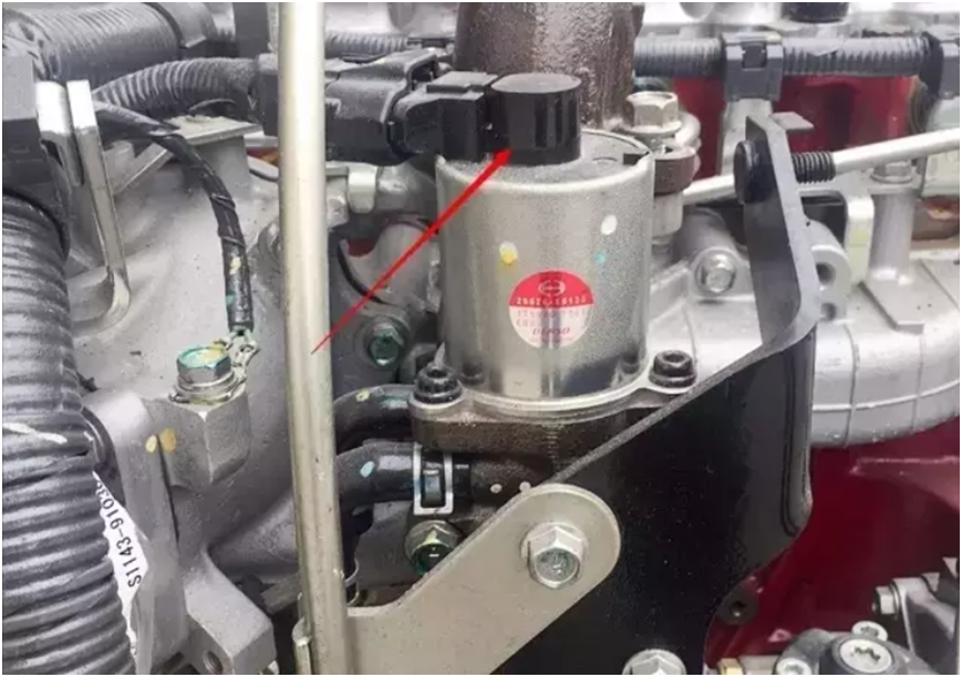
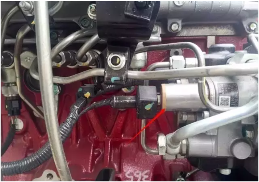
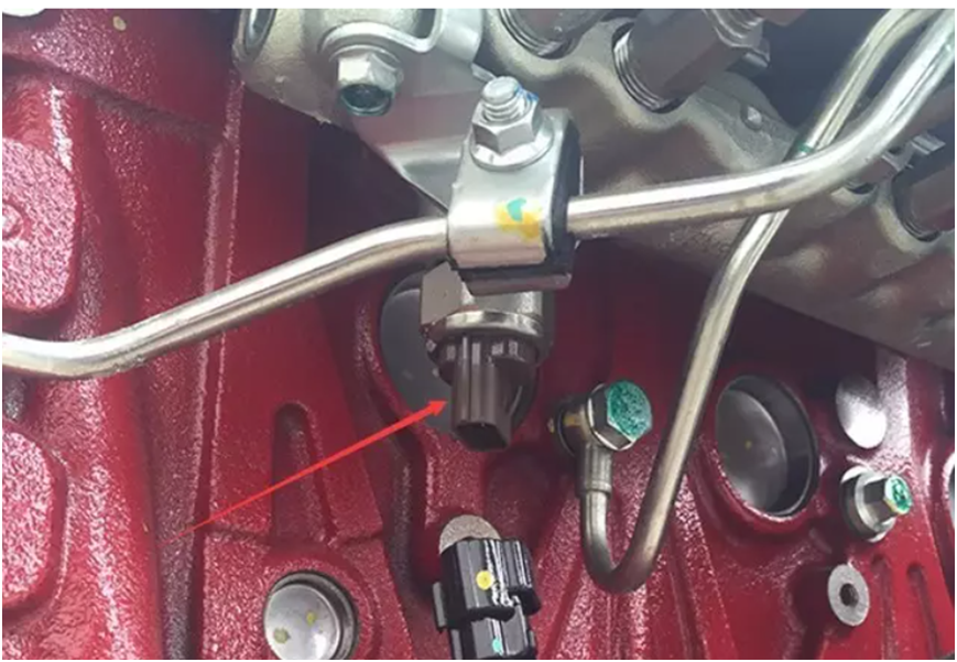
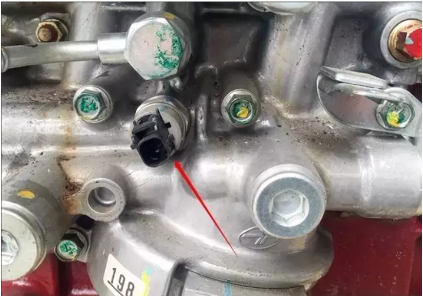
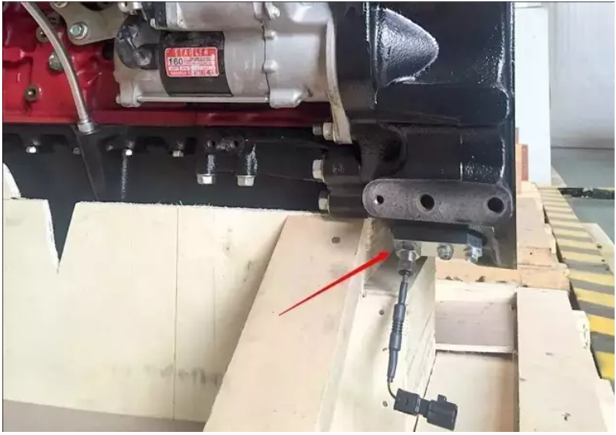
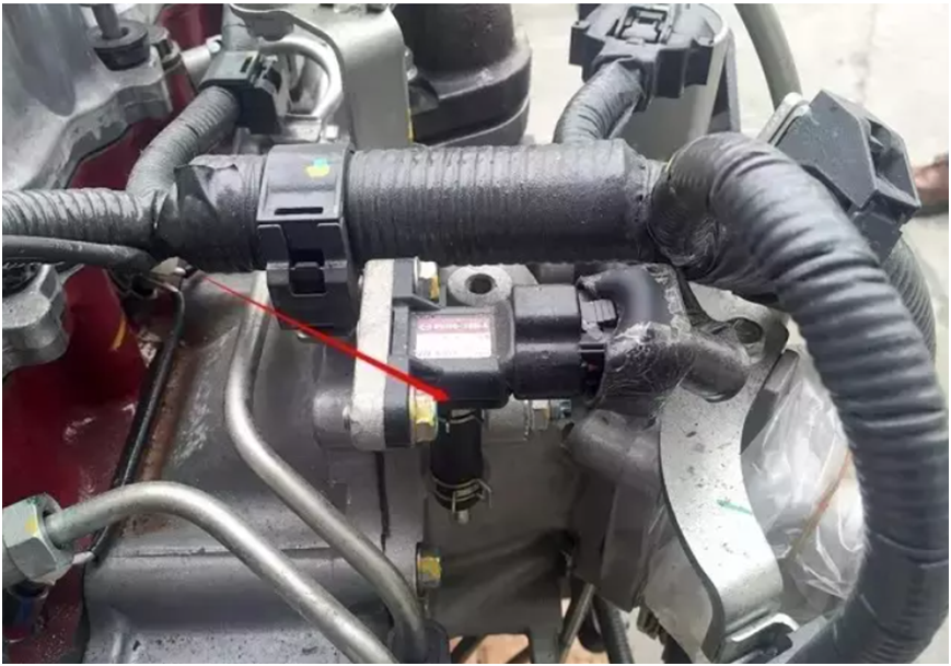
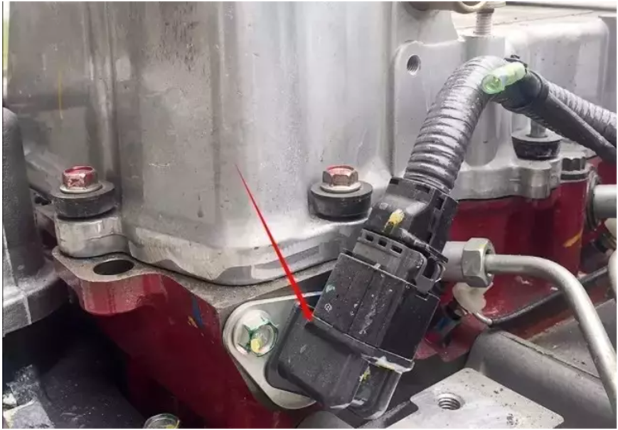
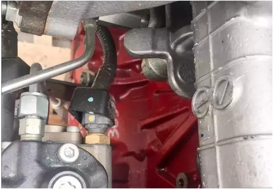
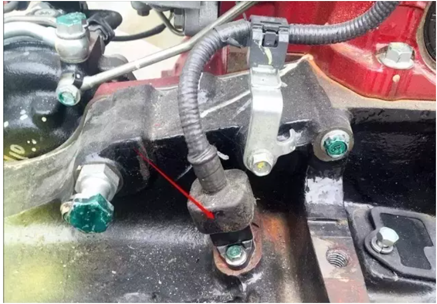
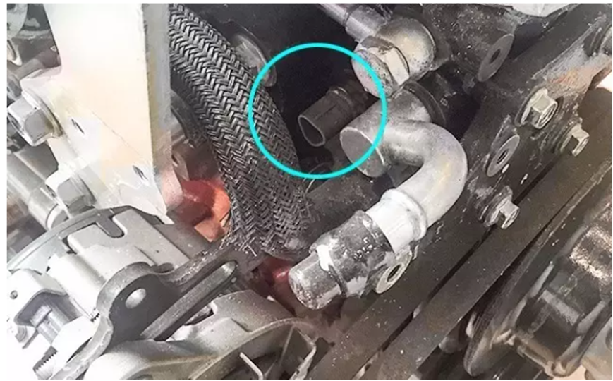 Figure 10: Water Temperature Sensor on the Thermostat Housing