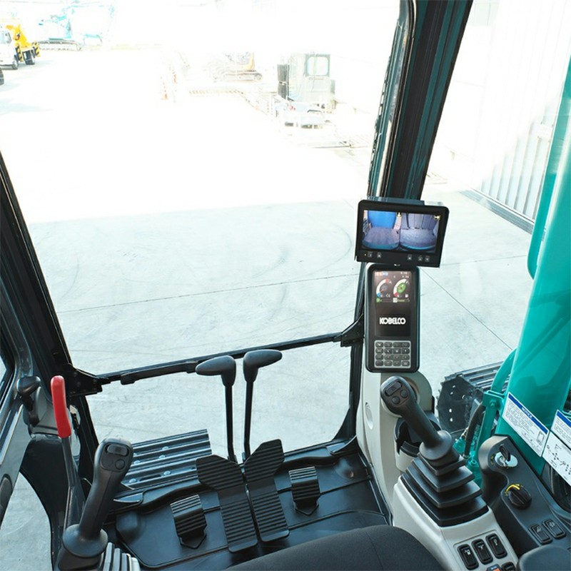
Kobelco Generation 10 Excavator Display Functions & A-B-C Mechatro Calibration Guide
In today’s blog post, we’ll provide a detailed overview of the ABC electromechanical adjustment for the Kobelco Model 10 excavator. However, based on practical experience, if previous issues with the excavator—such as problems with the relief valve, sensors, or solenoid valves—have not been resolved, attempting to perform the electromechanical adjustment on your own is likely to fail.
1. Kobelco Gen 10 Instrument Display & Switch Layout
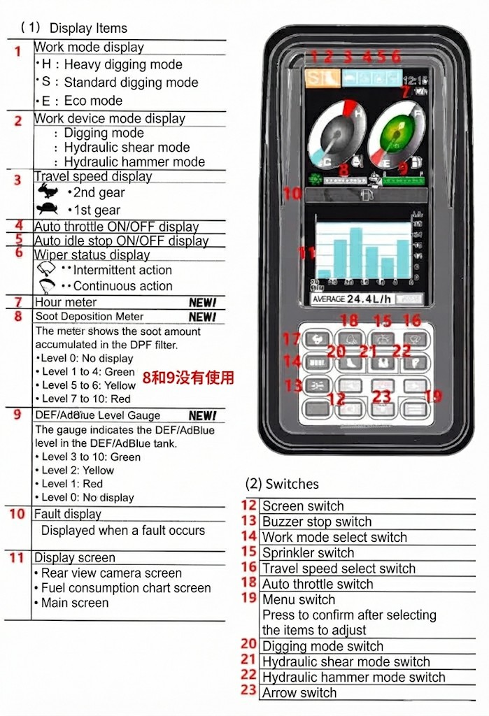
10 Excavator Displays
2. A-Calibration: Engine Adjustment (ADJUST OUTPUT)
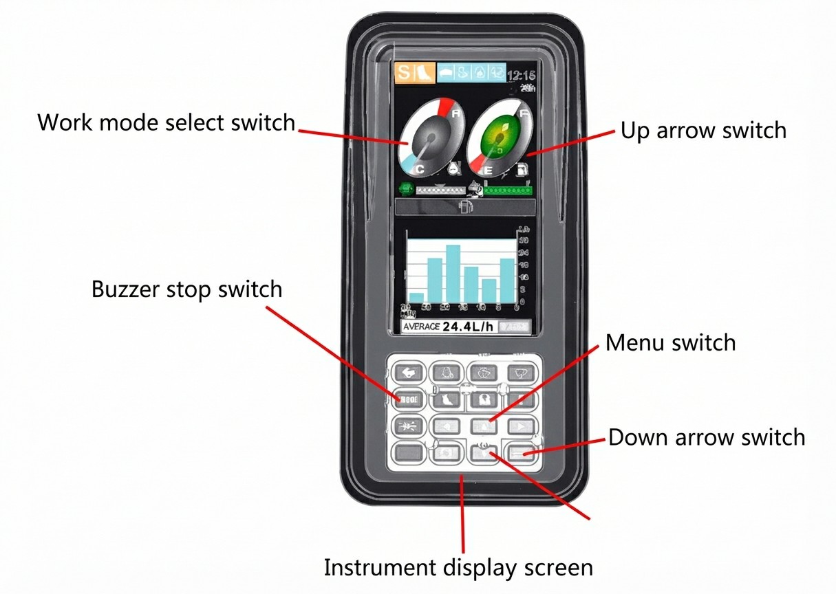
Initiation Mode: Press and hold the Work Mode Select Switch while turning the starter key switch to the ON position. Hold this state for 5 to 10 seconds, then release. (Do not start the engine, as starting will bypass the calibration menu).
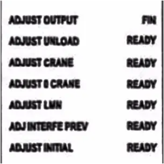
Access Calibration Select Screen: Press and hold the Buzzer Stop Switch for approximately 5 seconds, then release. The screen will display the adjustment menu. If no calibration data is stored in the mechatro controller, it displays "READY"; if previously calibrated, it displays "FIN". Note that the control lever lock solenoid is automatically released during this process, disabling regular machine operations.
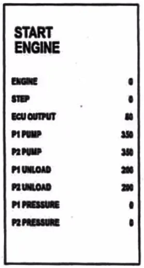
Start Engine Prompt: Press the Menu Switch until the screen displays the "START ENGINE" diagnostic parameter screen, showing engine RPM, P1/P2 pump pressures, and throttle command voltage step values.
3. B-Calibration: Hydraulic Pump Adjustment (ADJUST UNLOAD / MEMORY PUMP)
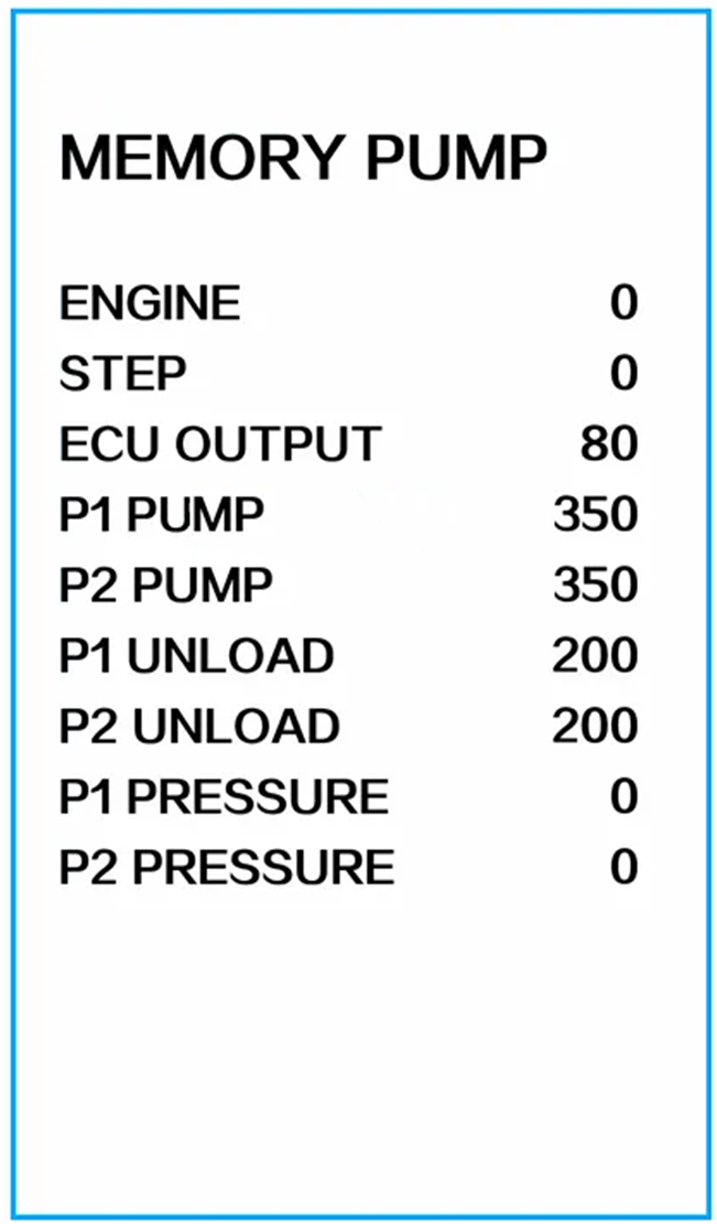
The system automatically transitions from engine adjustment to pump adjustment:
The engine speed automatically increases from Low idle to High idle.
The unload proportional valve and pump proportional valve actuate to increase hydraulic pump load.
The display shows engine RPM, P1 and P2 pump pressures, and proportional valve current command values.
Once the rated engine speed is detected, pump adjustment concludes automatically. (Note: Pressing the buzzer stop switch during this screen aborts adjustment, writes default values, and skips unload adjustment).
4. C-Calibration: Unload Valve Adjustment
The final phase calibrates the unload valves:
The system transitions automatically from pump adjustment to unload valve adjustment, actuating the unload proportional valves to detect pump pressures.
Monitor engine RPM, P1/P2 pump pressures, and unload proportional valve current values on screen.
When the unload proportional valves reach designated target values, adjustment concludes automatically, returning the engine to throttle-potentiometer-matched speeds.
Verification: Normal adjusted current values for P1 and P2 unload proportional valves typically fall within the 520 to 635 mA range.
Finally, shut down the engine. All calibration data is stored automatically.
⚠️ Professional Maintenance Warning
Improper self-calibration without resolving underlying hydraulic restrictions, pressure drops, or electrical sensor faults can lead to sluggish machine performance or system error codes[cite: 8]. If calibration values repeatedly fail to normalize, consult a certified Kobelco technician.