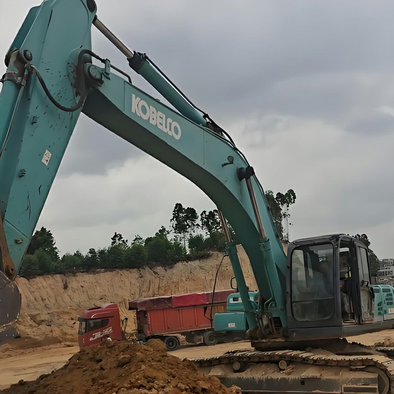
Kobelco Model 10 Excavator Fuse Box Diagram, Layout & Troubleshooting Guide
If your Kobelco Model 10 excavator experiences electrical malfunctions, sudden component shutdowns, or display errors, this is usually caused by a blown fuse.
1. Kobelco Model 10 Fuse Box Layout & Amperage Table
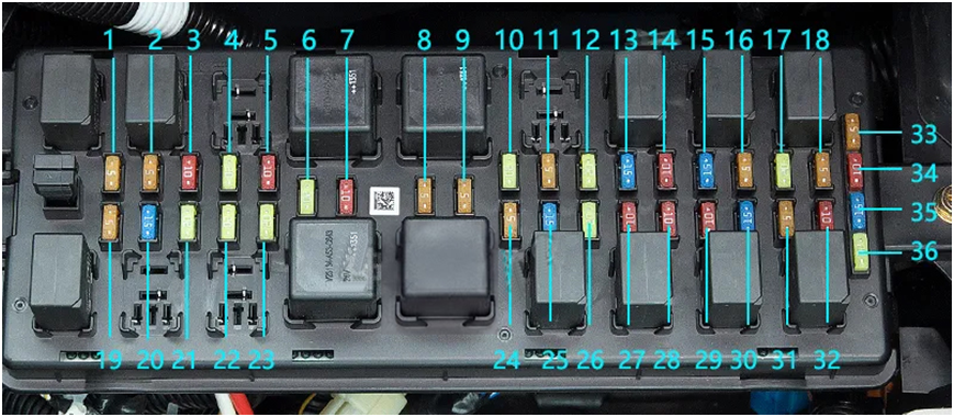
The fuse box for Kobelco Model 10 excavators contains 36 circuits controlling critical functions like the ECU, hydraulic control units, working lights, and air conditioning. Refer to the table below for exact amperage and circuit assignments:
| No. | Amperage | Circuit Name / Function | No. | Amperage | Circuit Name / Function |
|---|---|---|---|---|---|
| 1 | 5A | Mechatro Controller (Spare) | 19 | 5A | Cabin Light, Radio / Tuner |
| 2 | 5A | IT Controller | 20 | 15A | Fuel Supply Pump |
| 3 | 10A | Auto Greasing System | 21 | 20A | Start Switch |
| 4 | 20A | Working Light | 22 | 20A | Cab Working Light |
| 5 | 10A | Solenoid Valve, LMN / BH | 23 | 20A | Cab Working Light |
| 6 | 20A | Wiper | 24 | 5A | Air Conditioner |
| 7 | 10A | DC-DC Converter | 25 | 15A | Air Conditioner |
| 8 | 5A | Multi-Display Monitor | 26 | 20A | Option 1 |
| 9 | 5A | Air Conditioner | 27 | 10A | Horn |
| 10 | 20A | Travel Alarm, One-way Call | 28 | 10A | Option 3 |
| 11 | 5A | Camera DC-DC Converter | 29 | 10A | Option 4, Controller |
| 12 | 20A | Flashing Light (Beacon) | 30 | 15A | Engine Controller (ECU) |
| 13 | 15A | Roof Window Wiper | 31 | 5A | Relay |
| 14 | 10A | Radio / Tuner | 32 | 10A | Control Lever Lock |
| 15 | 15A | Engine Controller (ECU) | 33 | 5A | Spare Fuse |
| 16 | 5A | Mechatro Controller | 34 | 10A | Spare Fuse |
| 17 | 20A | Mechatro Controller | 35 | 15A | Spare Fuse |
| 18 | 5A | Option (Manual Controller) | 36 | 20A | Spare Fuse |
2. When to Inspect or Replace Fuses
Circuit Failure: If a specific electrical component (such as the windshield wiper, horn, or air conditioner) stops working unexpectedly, inspect its designated fuse.
Physical Corrosion: If you notice white powder buildup from corrosion, or loose connections between the fuse and the fuse terminal box, replace the unit immediately.
3. How to Safely Access and Replace Fuses
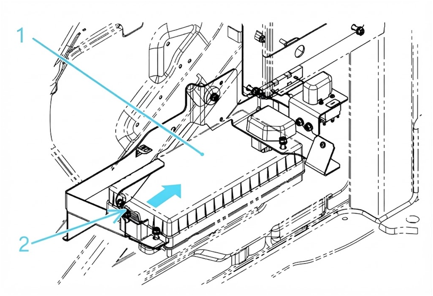
The fuse box is conveniently located inside the cab on the right-hand side. Follow these steps to perform a safe replacement:
Step-by-Step Replacement Procedure
Turn Off Power: Always turn the starter key switch to the "OFF" position before handling any electrical components.
Remove the Cover: Locate the fuse box cover on the right side of the operator's seat. Push the locking tab (2) inward to release the lock, then lift and remove the cover (1).
Extract the Fuse: Use a specialized fuse puller tool to cleanly pull the damaged fuse out of the fuse block. Avoid using improper metal tools that could cause a short circuit.
Install the New Fuse: Insert a brand new fuse matching the exact amperage and model specification. Note that spare fuses (Numbers 33 through 36) are conveniently stored on the inside of the fuse box cover.
Secure the Cover: Once replacement is complete, firmly snap the fuse box cover back into place to prevent dust and moisture infiltration.
⚠️ Important Maintenance Warnings
Match Amperage Ratings: Always replace a blown fuse with one of the exact same capacity and color rating. Installing a higher amperage fuse can severely damage the excavator's electrical wiring harness and control units.
Frequent Blowouts: If a newly replaced fuse blows out repeatedly within a short timeframe, it indicates an underlying short circuit or electrical fault in that harness loop.